Table of Contents
ToggleIntroduction to Electrical Measuring Instruments
Electrical measuring instruments are devices used to measure various electrical quantities such as voltage, current, resistance, power, frequency, and energy. These instruments play a vital role in designing, testing, troubleshooting, and maintaining electrical circuits and systems. From small electronics projects to large-scale power systems, the importance of accurate measurement cannot be overstated. Understanding these instruments is fundamental for students, professionals, and hobbyists alike.
Importance of Measurement in Electrical Engineering
In electrical engineering, precise measurement is the key to ensuring system reliability, safety, and efficiency. Measurements help engineers:
Validate the performance of circuits.
Detect and isolate faults.
Monitor power consumption.
Ensure compliance with standards.
Design energy-efficient systems.
For example, a slight overcurrent in a motor can lead to overheating and damage if not detected early. Instruments like ammeters help monitor such parameters in real-time.
Classification of Measuring Instruments
Electrical instruments are broadly classified based on their functionality and type of measurement.
By Function:
Indicating instruments: Provide instantaneous reading (e.g., voltmeter).
Recording instruments: Keep a record over time (e.g., data loggers).
Integrating instruments: Measure cumulative quantity (e.g., energy meters).
By Measurement Quantity:
Voltage: Measured by voltmeters.
Current: Measured by ammeters.
Resistance: Measured by ohmmeters.
Power: Measured by wattmeters.
Multi-functional: Measured by multimeters.
By Technology:
Analog: Use mechanical motion (e.g., moving coil instruments).
Digital: Use electronic displays and microcontrollers for processing.
Understanding the classification helps users choose the right instrument for specific applications.

Multimeter: The Universal Tool
What is a Multimeter?
A multimeter is a versatile instrument that can measure multiple electrical parameters including voltage, current, and resistance. It is commonly used in labs, industries, homes, and fieldwork. Also called a VOM (Volt-Ohm-Milliammeter), this device combines the functionality of several meters into one compact unit.
Types of Multimeters
There are two main types of multimeters:
Analog Multimeter: Uses a moving coil mechanism with a needle that deflects over a scale to indicate readings. These are less accurate and more difficult to read but preferred in situations where voltage fluctuations need to be monitored.
Digital Multimeter (DMM): Displays readings on an LCD screen and is the most commonly used type today. It offers higher precision, auto-ranging features, and additional functionalities like diode testing and continuity checking.
Features and Functions
Most digital multimeters include the following features:
DC Voltage Measurement (0-1000V)
AC Voltage Measurement (0-750V)
DC Current Measurement (µA to A range)
AC Current Measurement
Resistance Measurement (Ohms)
Diode Test Mode
Continuity Testing (with buzzer)
Capacitance and Frequency Measurement (advanced models)
Temperature Measurement (with thermocouple probe)
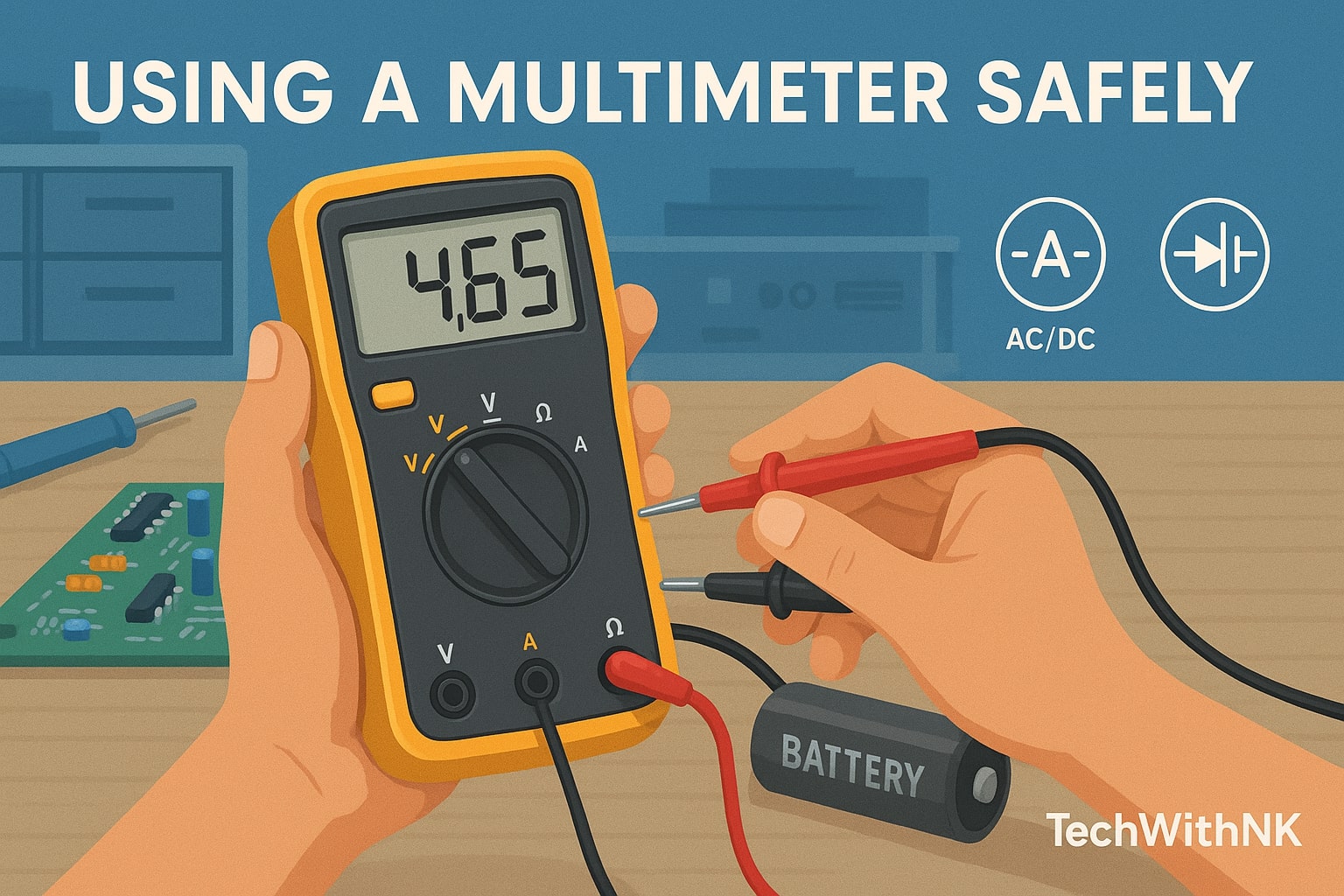
How to Use a Multimeter
Select the mode: Turn the dial to the type of measurement (V, A, Ω).
Insert the probes: Black lead to COM, red lead to VΩmA or 10A as required.
Connect the probes: For voltage/resistance, in parallel; for current, in series.
Read the value: On the digital screen or scale.
Turn off after use: To preserve battery and safety.
Safety Tips
Always begin with the highest range and then lower.
Never use in wet environments or with wet hands.
Avoid touching metallic probe tips.
Disconnect power when measuring resistance.
Replace damaged probes or cracked meters immediately.
Real-Life Use Cases
Checking wall socket voltage.
Measuring battery voltage.
Detecting blown fuses.
Troubleshooting PCBs.
Checking electrical continuity in home appliances.

Ammeter: Measuring Electric Current
Principle of Operation
An ammeter measures the flow of electric current in a circuit, expressed in amperes (A). It works on the principle that current passing through a conductor generates a magnetic field. This field interacts with a coil to deflect a needle (in analog) or convert into a digital reading.
Types of Ammeters
Moving Coil Ammeter: Suitable for DC current. It uses the D’Arsonval movement to deflect a pointer.
Moving Iron Ammeter: Can measure both AC and DC. It uses a coil to magnetize a piece of iron.
Digital Ammeter: Uses ADC (analog-to-digital converter) to show current values digitally.
Clamp Meter: A non-contact ammeter that measures current by sensing the magnetic field around a conductor. Useful for high-current measurements without circuit break.
Connection in Circuit
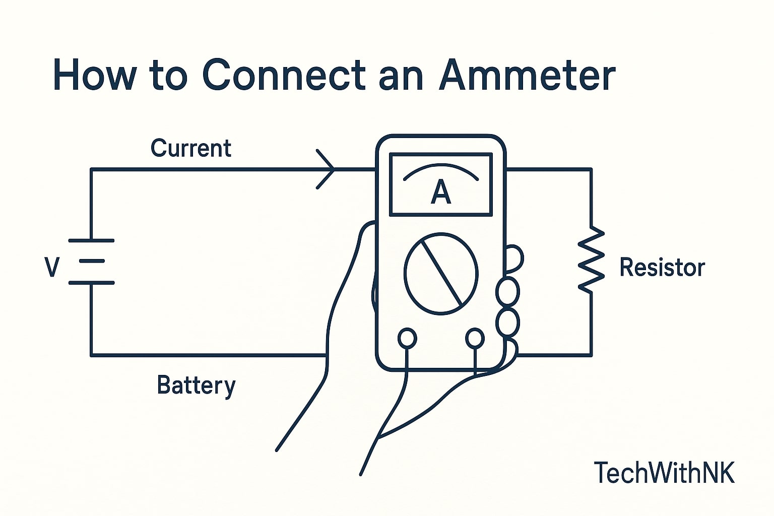
An ammeter must be connected in series with the load so the entire current passes through it. It has very low internal resistance to minimize voltage drop.
Precautions While Using
Never connect an ammeter across voltage source.
Use appropriate current range.
Avoid prolonged current overloading.
Disconnect when not in use.
Voltmeter: Measuring Voltage
Working Principle
A voltmeter measures the potential difference between two points. It functions by placing a high-resistance element in series with the internal moving coil or digital circuit so that very little current is drawn from the circuit under test.
Types of Voltmeters
Analog Voltmeter: Uses deflection of a pointer. Can be moving coil (DC only) or moving iron (AC/DC).
Digital Voltmeter (DVM): Converts input voltage to digital value using an ADC.
Electrostatic Voltmeter: For extremely high voltages (>30kV), commonly used in high-voltage labs.
Internal Resistance Concept
Voltmeter must have high internal resistance (usually in megaohms) so it does not load the circuit or alter the voltage across the test points.
AC vs DC Voltage Measurement
DC Voltage: Usually measured with direct polarity connection.
AC Voltage: Measured using RMS value. True-RMS meters provide more accurate results in case of non-sinusoidal signals.
Wattmeter: Measuring Power
What is Electrical Power?
Electrical power is the rate at which energy is consumed or generated in a circuit. For AC systems:
P = VIcos(φ), where φ is the phase angle between voltage and current.
Construction of Wattmeter
Wattmeters typically consist of:
Current Coil: Connected in series with load.
Voltage Coil: Connected across the load.
Moving Coil/Permanent Magnet: Causes needle deflection based on interaction of magnetic fields from both coils.
Types of Wattmeters
Dynamometer Wattmeter: Used in labs; suitable for both AC and DC.
Induction Wattmeter: Used in older power meters; AC only.
Digital Wattmeter: Microcontroller-based; provides precise readings.
Clamp Power Meter: Measures power without breaking the circuit; especially used in industrial setups.
How to Measure Power Using Wattmeter
Connect current coil in series with the load.
Connect voltage coil in parallel across the load.
Observe the deflection or digital reading.
Multiply reading by multiplying factor if applicable.
Application in Power Plants and Industries
Measuring input power to motors.
Monitoring load on generators.
Power factor correction.
Billing and energy audits.
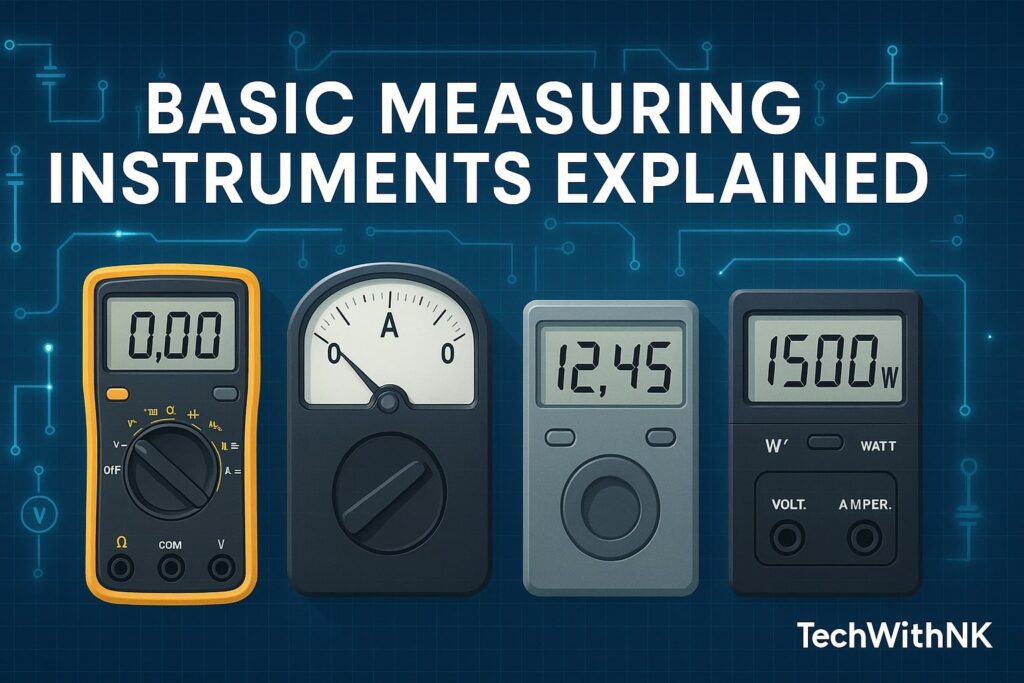
Key Differences: Multimeter vs Ammeter vs Voltmeter vs Wattmeter
Each instrument has its unique purpose and usage:
A multimeter is versatile and combines functionalities.
An ammeter specifically measures current and is used in series.
A voltmeter measures potential difference and is connected in parallel.
A wattmeter measures power using both voltage and current coils.
Real-World Examples and Case Studies
Multimeter in Home Repair: Troubleshooting a fan not working.
Ammeter in Solar System: Checking current from solar panels.
Voltmeter in Grid Substations: Monitoring line voltage.
Wattmeter in Industry: Measuring motor power consumption for performance tuning.

Instrument Calibration and Accuracy
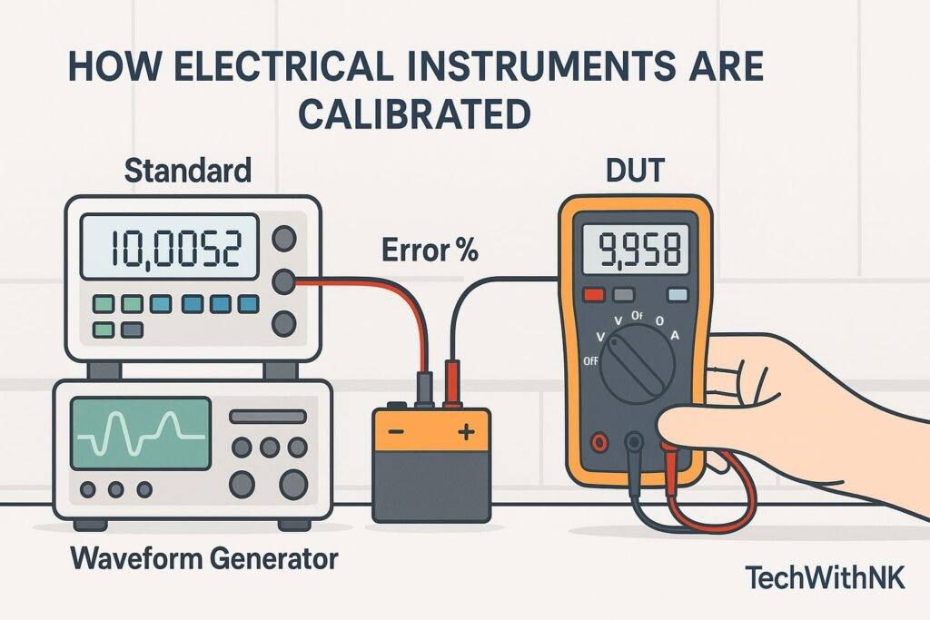
Calibration ensures that instruments give correct readings within acceptable tolerance. It involves comparing the instrument against a known standard.
Frequency: Annually or as specified.
Methods: Manual with standard instruments or automated test benches.
Impact: Uncalibrated instruments may lead to faulty diagnosis, energy loss, or safety hazards
Common Measurement Mistakes and How to Avoid Them
Using voltage mode to measure current: Can damage the meter.
Wrong probe placement.
Ignoring polarity.
Not zeroing analog meters before use.
Using auto-range in noisy environments.
Summary and Best Practices
Choose the right instrument for the job.
Understand connection rules: series for current, parallel for voltage.
Start with high range and reduce.
Avoid overloading meters.
Calibrate periodically.
Use insulated tools and follow safety standards.
Conclusion
Understanding and mastering basic electrical measuring instruments is essential for anyone working in electrical domains. These tools form the backbone of electrical diagnostics, design, and maintenance. With evolving technology, digital and smart instruments are replacing analog counterparts, making measurements more accurate, efficient, and user-friendly.
Whether you’re a student in a lab or an engineer in a power plant, a solid grasp of multimeters, ammeters, voltmeters, and wattmeters will empower you to work confidently and safely.
Can a multimeter replace an ammeter or voltmeter?
Yes, a multimeter includes both functions and more.
What is the safest way to measure current?
Using a clamp meter is safest as it doesn’t require circuit breaking.
Can I measure power using a multimeter?
No, unless it is a power meter DMM. Use a wattmeter.


