Table of Contents
Toggle1. 🔌 Introduction to Ohms Law And Circuit Theorems
Electric circuits are the foundation of modern electronics. Whether you’re designing a smartphone, building an electric car, or working in a thermal power plant, understanding Ohms Law and Circuit Theorems is vital.
In this guide, you’ll explore:
The theory behind these laws
Practical applications in circuits
Real-world industrial examples
Problem-solving techniques
2. ⚡ What is Ohm’s Law?
Ohms Law defines the relationship between voltage, current, and resistance in a conductor.
🔸 Statement:
“The current flowing through a conductor between two points is directly proportional to the voltage across the two points, provided the temperature remains constant.”
🔹 Formula:
V=I×RV = I \times RV=I×R
Where:
V = Voltage (Volts)
I = Current (Amperes)
R = Resistance (Ohms)
🧠 Memory Tip:
VIR Triangle
Cover any one quantity to find the other:
V = IR
I = V/R
R = V/I
3. 📐 Mathematical Expression & Unit Relationships
1 Volt = 1 Ampere × 1 Ohm
Resistance (R) = Voltage (V) / Current (I)
Example Calculation:
A bulb has 6V applied across it and draws 2A current.
R=V/I=6/2=3 ΩR = V / I = 6 / 2 = 3 \, \OmegaR=V/I=6/2=3Ω
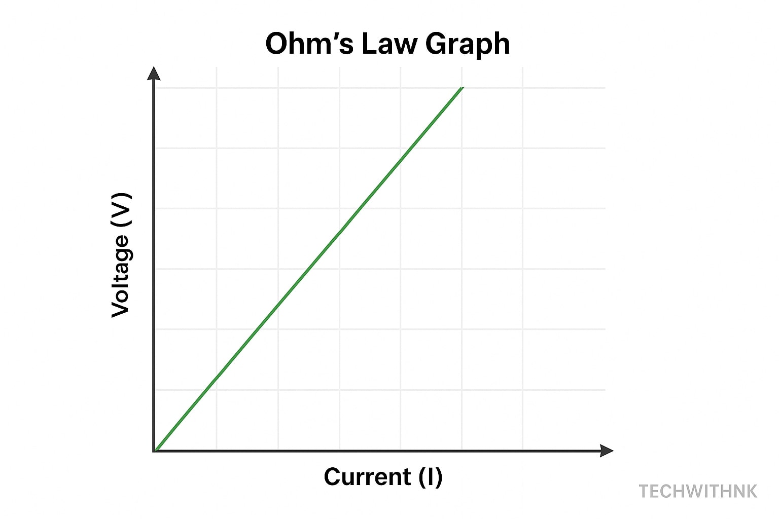
4. 📊 Graphical Representation of Ohm’s Law
➤ Voltage vs Current Graph
A straight line through origin (for a resistor), slope = Resistance (R)
5. 🛠️ Applications of Ohms Law in Real Life
Electrical wiring design
Power rating of appliances
Battery charging circuits
EV charging systems
Voltage regulation in solar inverters
Industrial Example:
In thermal power plants, heaters and sensors are designed using Ohms Law to avoid overcurrent and maintain temperature thresholds.
6. ⚠️ Limitations of Ohms Law
Not applicable to non-linear devices (e.g., diodes, transistors)
Temperature changes affect resistance
Not valid for high-frequency AC circuits
7. 🔄 Kirchhoff’s Laws Explained
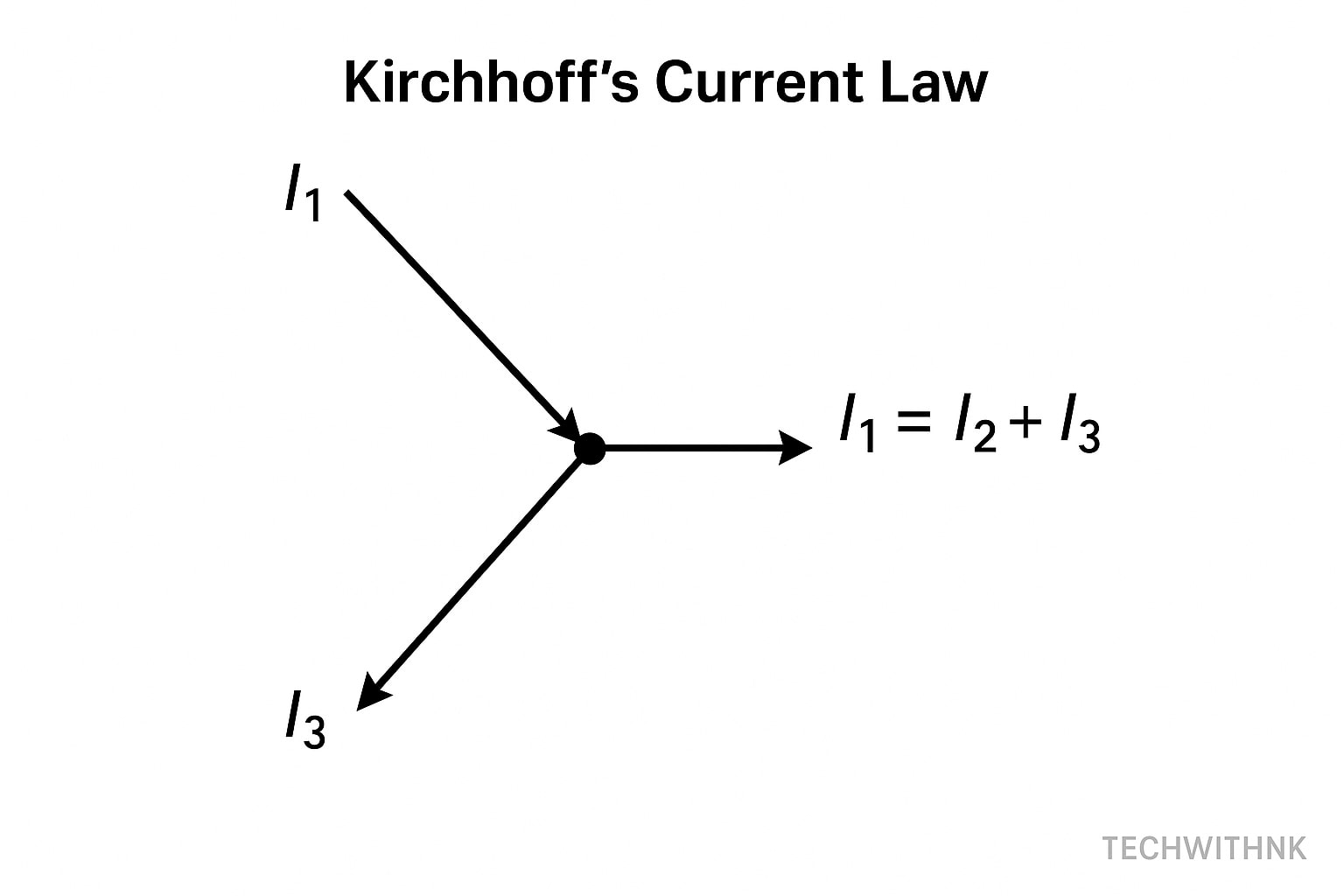
Kirchhoff’s Current Law (KCL)
“The algebraic sum of currents entering a node (or junction) is zero.”
➤ Formula:
∑Iin=∑Iout
Example:
At a node: I1 enters, I2 and I3 leave
I1=I2+I3I1 = I2 + I3I1=I2+I3
Kirchhoff’s Voltage Law (KVL)
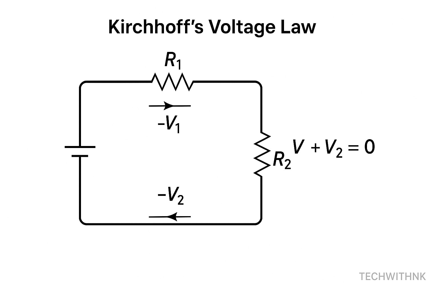
“The algebraic sum of voltages in a closed loop is zero.”
➤ Formula:
∑V=0
Example:
Battery 12V, Resistors R1 and R2 drop 5V and 7V
+12V−5V−7V=0+12V -5V -7V = 0+12V−5V−7V=0
8. 🔁 Mesh Analysis Technique
Used in circuits with multiple loops (meshes) to find unknown currents.
Steps:
Identify meshes.
Apply KVL in each loop.
Solve simultaneous equations.
9. 🔂 Nodal Analysis Technique
Used to calculate node voltages in complex circuits.
Steps:
Select a reference (ground) node.
Apply KCL at remaining nodes.
Solve equations for unknown voltages.
10. 🔀 Superposition Theorem
In linear circuits with multiple sources:
“The total current or voltage is the algebraic sum of the effects caused by each source independently.”
Deactivate:
Voltage source → Replace with short
Current source → Replace with open
11. 🔋 Thevenins Theorem
“Any two-terminal network can be replaced with an equivalent voltage source and series resistance.”
Steps:
Remove load.
Find open-circuit voltage (Vth).
Find resistance (Rth) with sources deactivated.
Replace the circuit with Vth and Rth.
12. ⚡ Norton’s Theorem
Lorem ipsum dolor sit amet, consectetur adipiscing elit. Ut elit tellus, luctus nec ullamcorper maA
Similar to Thevenin’s but uses current source:
“Any two-terminal network can be replaced with a current source in parallel with resistance.”
ttis, pulvinar dapibus leo.
13. 📈 Maximum Power Transfer Theorem
“Maximum power is transferred when load resistance equals source (Thevenin) resistance.”
RL=Rth
14. 🧮 Millman’s Theorem
Used for simplifying parallel branches with voltage sources and resistors.
BV=∑(Vi/Ri)/∑(1/Ri)
15. 🖥️ Circuit Simulation Tools for Beginners
LTspice – Free SPICE simulator
Tinkercad Circuits – Browser-based for students
Proteus – Widely used in academics
Pspice – Industry-grade simulation
Multisim – Visual and easy drag-drop interface
16. 📋 Summary & Quick Revision Table
| Theorem/Law | Use Case | Method |
|---|---|---|
| Ohm’s Law | Basic calculations | V = IR |
| KCL | Node analysis | ΣI = 0 |
| KVL | Loop analysis | ΣV = 0 |
| Mesh | Loops | KVL |
| Nodal | Nodes | KCL |
| Superposition | Multiple sources | Source deactivation |
| Thevenin | Equivalent circuit | Vth & Rth |
| Norton | Equivalent circuit | In & Rn |
| Max Power Transfer | Load matching | R_L = R_th |
✅ Conclusion
Understanding Ohms Law and the Basic Circuit Theorems is essential for every electrical and electronics engineer. These laws are not just academic—they’re the tools you’ll use daily in analysis, design, troubleshooting, and innovation.
Whether you’re working with simple LEDs or managing power grids, these principles remain relevant and powerful. With practice and problem-solving, you’ll gain the intuition needed to master circuits from the basics to the most complex systems.
What is the importance of Ohms Law in electrical engineering?
It’s the foundation for understanding current, voltage, and resistance relationships in all circuits.
Can Ohms Law be used for AC circuits?
Yes, but you must use impedance (Z) instead of resistance.
What is the difference between KVL and KCL?
KVL is for voltage loops; KCL is for current nodes.

